Fitting workspace
Deze inhoud is nog niet vertaald.
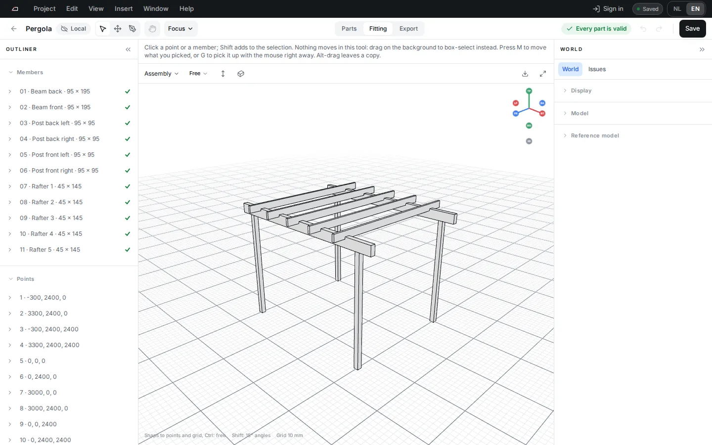
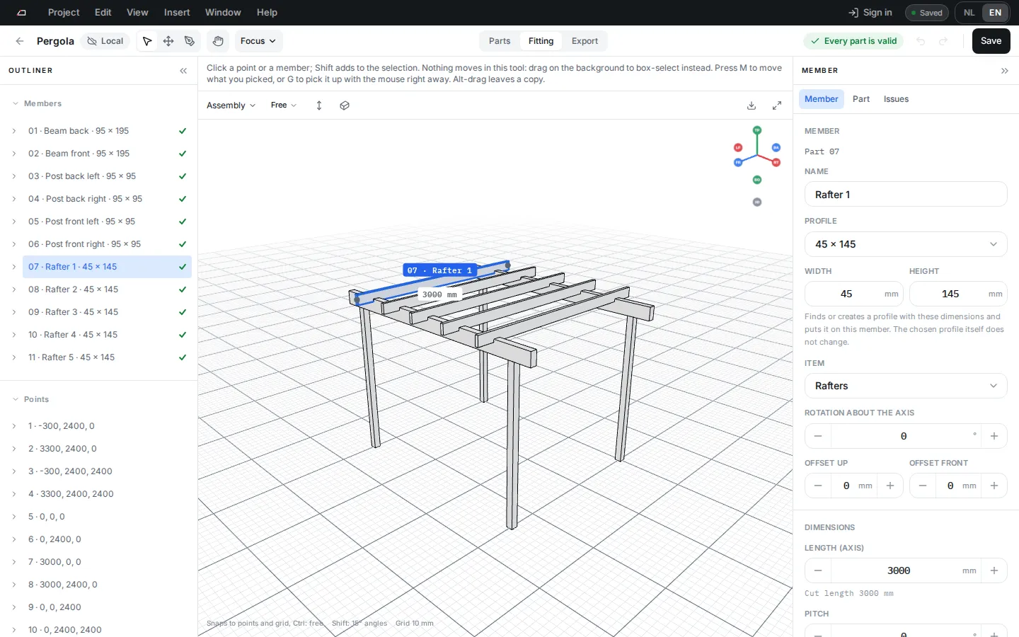
In Fitting you draw the frame as members between points. Each member becomes a part in the parts list straight away, with its cuts and joints worked out from how it meets the others.
Draw and edit
Section titled “Draw and edit”| Tool | Key | What it does |
|---|---|---|
| Select | V | Click to select, Shift to add, drag the background to box-select. |
| Move | M | Drag the selection. X, Y or Z locks an axis. |
| Draw | D | Drag to draw a member. Keep going to chain members; Esc or Enter ends the chain. |
| Grab | G | The selection follows the mouse. Click to put it down. |
Turn on View > Snap to beam axes (; then A) and a point you move lands on the centre line of a beam the mouse passes over, so the member you drag ends on that beam. The beam lights up in blue and the label names it. Hold Cmd (Ctrl on Windows) to place freely.
Hold Alt while you drag to leave a copy. Insert > Construct has Frame, Repeat, Shape along sections, Connect, Script and Patterns. A script lets an assistant draw members from a rule; see Draw with a script.
Edit several members at once
Section titled “Edit several members at once”Select several members: Shift-click them, drag a box, or right-click one and choose Select similar. The Members tab then shows what they share.
- A field where the members differ reads Mixed. Pick or type a value to give it to all of them.
- Profile, Width, Height, Item, Rotation about the axis and the offsets work this way. A new width or height keeps each member’s own strength class.
- Lock beam length fixes the length of every selected member at once, and a second press frees them again. ; then L does the same.
- Move the end of a locked member and it swings round the other end at the same length. Where two locked members meet at the point you move, it follows the mouse along the circle on which both lengths hold. Three locked members at one point hold it still. Type a number while the end swings and it turns that many degrees instead; - turns it the other way.
- Locking a member that a pattern made is not a change to the pattern: the lock stays when the pattern updates.
- Each change is one step to undo.
- A part you changed by hand in the Part tab keeps its own values. Click Derive again to include it.
How joints are made
Section titled “How joints are made”- Members that share a point meet at a node. Pick the node joint: Automatic, Miter, Butt, Through 1 or Through 2.
- A member end that stops on another member is cut to that member’s face. The other member is not cut, unless you let the end into it.
- To let ends into the beam they land on, select the members (all joists between two main beams at once) and under Ends on a beam set Joint to Housed in the beam with a Depth, in millimetres or, under Depth as, as a share of the beam’s thickness. The end runs that far into the beam, which gets a housing of exactly that shape. To let every smaller member into the larger one it lands on, switch Smaller members on larger ones under Model to Let in; an end you set yourself keeps its own setting. For an end arriving at an angle, choose Sawn along the face (the housing is equally deep everywhere) or Sawn square (the end is cut straight across and the housing takes the angle, deeper on one side). The point panel has them for each end too. With BVN or BVX as the machine, an angled end stays flush, with a warning, unless sawn square and angled in plan and slope (a 3D pocket). For one member, each end there also offers Choose a joint: a housed tenon, a knife plate and more, see A joint at a member’s end.
- Crossing members can get a Half lap or a Pass-through. Where two members cross at the same height, the half lap’s section says which one lies over the other; Turn the lap over swaps them.
- Set Machining compatibility in World properties to BVN or BVX to keep joints within that format; a joint it cannot write keeps its overlap in view.
- A crossing can also get a joint you design, square, at an angle or with a member rolled (see Joints at an angle). Select one of the two members (or both) and click Design a joint…, or open Joint and pick a starting shape under New joint: half lap, housing, pinned half lap, pegged housing, knife-plate slit or blank. The designer shows both parts in 3D, cut as you edit: outlines, housings, 3D housings, drillings, a peg through both parts, rebates, grooves and saw cuts, each size fixed or tied to the timber so the joint fits other crossings. Your joints are listed under Joints in the outliner. See Design your own joint.
Panels and views
Section titled “Panels and views”- The outliner lists Members and Points. Parts without a place lists parts that are not in the model yet; click Place in model.
- The right panel is named after what you select: World, Member, Point and so on, with Part and Issues next to it. A project made from a building system has a Configuration tab first, with its settings.
- Press 1, 3 or 7 for the front, right or top view, and 0 for the free view.
- View > 3D colours picks how the 3D views paint parts. Signal shows every machined face in orange, and uses a dark background in dark mode. Paper is the ink drawing on white. Customise colours sets your own background, edges, wood, end grain and machined faces. Selection stays blue and warnings stay red.
Reference images and models
Section titled “Reference images and models”- A reference image sits behind one view: Front, Back, Right, Left, Top or Bottom. Add one with Insert > Reference image…, with Reference image for this view… in a pane’s view menu, or by dropping an image on the window.
- Click an image to select it. Drag it to move it, and drag a blue handle to resize it: it keeps its proportions. Hold Alt (⌥ on a Mac) while you drag to leave a copy.
- Drag the round handle above an image to turn it; hold Shift for steps of 15°. Or press G, R or S to move, turn or scale it with the mouse, then click to put it down or press Esc to put it back.
- Crop cuts a share off each edge of an image. The rest stays exactly where it was, so you can undo a crop by setting it back to 0.
- An SVG drawing works as a reference image too: drop it on the window or choose it like a photo.
- Set to scale: click two points on the image and type their real distance.
- The free view, a view in perspective and the phone show the image too, standing behind the frame (a plan lies at its foot). Move and resize it in a flat view of its own side. Export view draws it behind the frame in SVG and PNG.
- Lock (Ctrl Shift L) lets clicks pass through the image, so you can draw and box-select on top of it.
- An image stays on the device you added it on. Another device shows its outline and Choose file….
- Select the reference model under References in the outliner, or with Move in its section of World. Drag an arrow to move it. Press R for the ring and drag it to turn the model.
- Drag a construction plane by its edge to move it, and by a blue handle to resize it. Drag the middle dot of a dimension to move its line.